At this point, the physical build of our beginner 5-inch FPV drone is almost complete.
We have already installed:
- the frame
- the motors
- the ESC
- the flight controller
- the battery lead
- the capacitor
- the FPV camera
- the VTX
- the VTX antenna
- the ExpressLRS receiver
This is a major milestone.
But before we move into Betaflight configuration, receiver setup, motor testing, or any software-related step, we need to stop and inspect the entire drone carefully.
This chapter is not about adding new components.
This chapter is about verification.
Before powering the drone normally, we must confirm that:
- the wiring is correct
- polarity is correct
- there are no short circuits
- no wires are loose
- the VTX antenna is installed
- the receiver is connected correctly
- the drone is safe to power
This is one of the most important chapters in the entire build.
A careful inspection now can prevent:
- burned ESCs
- damaged flight controllers
- destroyed VTX units
- failed receivers
- smoke
- fire risk
- expensive beginner mistakes
In FPV, patience during inspection saves money, time, and frustration.
Why the Final Wiring Check Matters
Many FPV failures happen not because the parts are bad, but because something small was missed during assembly.
Common problems include:
- reversed polarity
- solder bridges
- loose strands of wire
- incorrect voltage pads
- missing ground connections
- VTX powered without antenna
- wires touching carbon fiber
- battery lead too close to propellers
- motor wires damaged by screws
- receiver TX/RX connected incorrectly
Most of these problems are preventable.
The final wiring check is the moment where we slow down and verify the build before applying full power.
This is the difference between guessing and building properly.
The Golden Rule Before Testing
Before doing any electrical test, remember:
remove all propellers
At this stage, propellers should still not be installed.
Never install propellers during:
- soldering
- wiring checks
- Betaflight setup
- receiver setup
- motor direction testing
- ESC testing
- failsafe testing
- bench configuration
Motors can spin unexpectedly during setup.
Without propellers, this is usually harmless.
With propellers installed, it can become dangerous very quickly.
For now:
no props
What We Are Checking
The final wiring check includes six main steps:
- Visual inspection
- Mechanical inspection
- Solder joint inspection
- Polarity verification
- Continuity test
- Smoke stopper power test
Each step has a specific purpose.
Do not skip any of them.
Step 1 — Visual Inspection
Start with a simple visual inspection.
Do not use power yet.
Do not connect a battery yet.
Place the drone on a clean table under good lighting and inspect everything slowly.
Look at the drone from:
- top
- bottom
- front
- rear
- left side
- right side
Use a phone camera if needed.
Sometimes small problems are easier to see when zooming in on a photo.
What to Look For Visually
Check for:
- loose wires
- exposed copper
- solder bridges
- damaged insulation
- wires touching carbon fiber
- wires near propeller paths
- loose screws
- missing screws
- crushed wires
- reversed connectors
- poor antenna placement
- components touching each other incorrectly
The goal is to catch obvious problems before using tools.
Step 2 — Check the Battery Lead
The battery lead is one of the most important parts of the build.
It carries full battery power from the LiPo to the ESC.
Inspect the XT60 lead carefully.
Check that:
- positive wire goes to positive pad
- negative wire goes to negative pad
- solder joints are strong
- insulation is not damaged
- wire is not under tension
- wire cannot reach propellers
- connector is secure
- capacitor is installed correctly
A mistake here can destroy electronics instantly.
Step 3 — Check Battery Polarity
Polarity means:
positive and negative orientation
On the ESC, the battery pads are usually marked:
+-
The red wire usually connects to positive.
The black wire usually connects to negative.
Never rely only on wire color if something looks unusual.
Always verify pad labels.
Reversed polarity is one of the fastest ways to destroy an FPV drone.
Step 4 — Check the Capacitor
The capacitor helps reduce voltage spikes and electrical noise.
But capacitors usually have polarity.
This means the positive and negative legs must be connected correctly.
Check that:
- positive leg is connected to positive battery pad
- negative leg is connected to negative battery pad
- capacitor is not loose
- legs are insulated if needed
- capacitor cannot hit propellers
- capacitor is not stressing the solder pads
The negative side of many capacitors is marked with a stripe.
If the capacitor is installed backwards, it can fail.
Step 5 — Check Motor Wires
Each motor has three wires connected to the ESC.
Inspect each motor wire carefully.
Check that:
- wires are soldered cleanly
- no strands are loose
- no solder bridges exist between motor pads
- wires are not cut by carbon fiber edges
- wires are not too tight
- wires are not in propeller paths
- wires are secured along the arms
At this stage, motor direction does not matter yet.
Motor direction will be configured later.
Right now, we only care about safe and clean wiring.
Step 6 — Check Motor Screws Again
This is very important.
Earlier, we talked about screw length.
Now check again.
Motor screws that are too long can touch the motor windings.
This can cause:
- short circuits
- motor damage
- ESC damage
- strange motor behavior
- smoke during power-up
Spin each motor by hand.
The motor bell should rotate smoothly.
There should be:
- no scraping
- no grinding
- no contact
- no unusual resistance
If a motor feels rough after installation, inspect the screws immediately.
Step 7 — Check the ESC and Flight Controller Stack
Inspect the stack carefully.
Check that:
- ESC is not touching carbon fiber
- flight controller is not touching ESC solder joints
- soft mounts are not crushed
- stack screws are secure
- ESC-to-FC harness is connected correctly
- no wires are pinched between boards
- USB port is accessible
- top plate does not press on the stack
The stack should be secure but not compressed.
The flight controller must be protected from excessive vibration.
Step 8 — Check the ESC-to-FC Harness
The harness between the ESC and flight controller is critical.
It carries important signals between both boards.
Check that:
- connector is fully inserted
- connector orientation is correct
- wires are not damaged
- wires are not pinched
- harness is not pulling tightly
- harness does not touch sharp carbon edges
Do not force connectors.
If a connector does not fit easily, check orientation.
Step 9 — Check the FPV Camera Wiring
Inspect the FPV camera wiring.
Check that:
- camera power is connected to the correct voltage pad
- camera ground is connected to GND
- camera video signal is connected to CAM or Video In
- wires are not loose
- camera cable is not crushed
- camera is mounted securely
- camera angle can still be adjusted
Do not connect the camera to VBAT unless the camera specifically supports full battery voltage.
Many cameras require 5V or 9V regulated power.
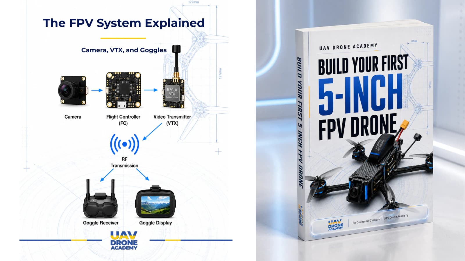
Step 10 — Check the VTX Wiring
The VTX is responsible for transmitting video to the goggles.
Check that:
- VTX power is connected to the correct voltage pad
- VTX ground is connected correctly
- VTX video wire is connected to Video Out or VTX pad
- SmartAudio or Tramp wire is connected to the correct pad
- VTX is mounted securely
- VTX has enough airflow or space
- VTX wires are not under tension
Most importantly:
make sure the VTX antenna is installed before powering the drone
Never power a VTX without an antenna connected.
This can damage the VTX.
Step 11 — Check the FPV Antenna
Inspect the FPV antenna and connector.
Check that:
- antenna is connected firmly
- connector is not loose
- antenna is not damaged
- antenna is clear of propeller paths
- antenna is not crushed by the top plate
- antenna is not completely blocked by carbon fiber
A poor antenna setup can create weak video signal and unreliable FPV performance.
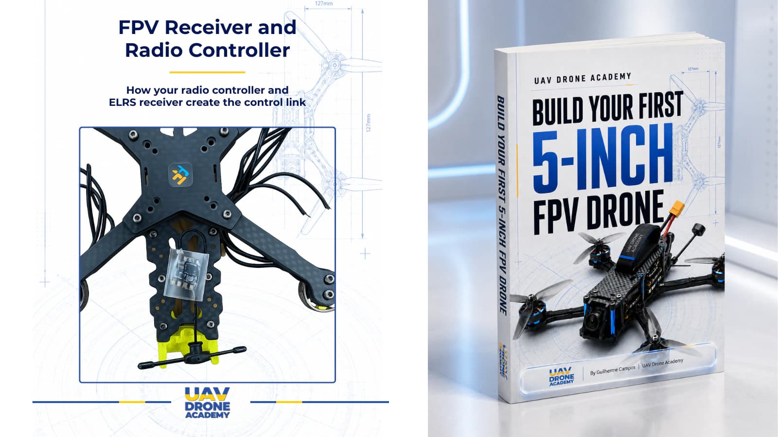
Step 12 — Check the ExpressLRS Receiver
Inspect the receiver wiring.
Most ELRS receivers require:
- 5V
- GND
- TX
- RX
Check that:
- receiver power is connected to 5V
- receiver ground is connected to GND
- receiver TX goes to flight controller RX
- receiver RX goes to flight controller TX
- receiver is mounted securely
- receiver antenna is properly placed
- wires are not too tight
Remember:
TX goes to RX
RX goes to TX
This is one of the most common beginner wiring mistakes.
Step 13 — Check Receiver Antenna Placement
The receiver antenna should not be buried inside carbon fiber.
Carbon fiber can weaken radio signal.
Good receiver antenna placement helps:
- signal reliability
- range
- link quality
- failsafe resistance
Avoid placing the antenna:
- directly under the battery
- next to high-current wires
- inside the frame center
- too close to the VTX antenna
- where it can be chopped by propellers
The antenna should be secure and protected.
Step 14 — Check Wire Routing
Now inspect the overall wire routing.
A clean FPV build should avoid loose wires.
Check that wires:
- do not touch propeller areas
- do not rub against sharp carbon
- do not pull on solder pads
- do not block the USB port
- do not press against the gyro
- do not interfere with the top plate
- are not excessively long or messy
Use zip ties, heat shrink, or tape carefully if needed.
Do not fully lock everything permanently until basic testing is complete.
But everything should already be safe enough for power testing.
Step 15 — Check for Exposed Conductors
Exposed copper can create shorts.
Inspect:
- motor wires
- signal wires
- receiver wires
- VTX wires
- camera wires
- capacitor legs
- battery lead
- solder joints
Use heat shrink or insulation where necessary.
Any exposed conductor that can touch carbon fiber or another pad is a risk.
Step 16 — Check Carbon Fiber Contact
Carbon fiber can conduct electricity enough to create problems.
Make sure:
- solder joints are not touching the frame
- ESC components are not touching carbon
- receiver pads are insulated
- VTX pads are insulated
- capacitor legs are insulated
- wires are not stripped where they touch the frame
This is especially important in tight builds.
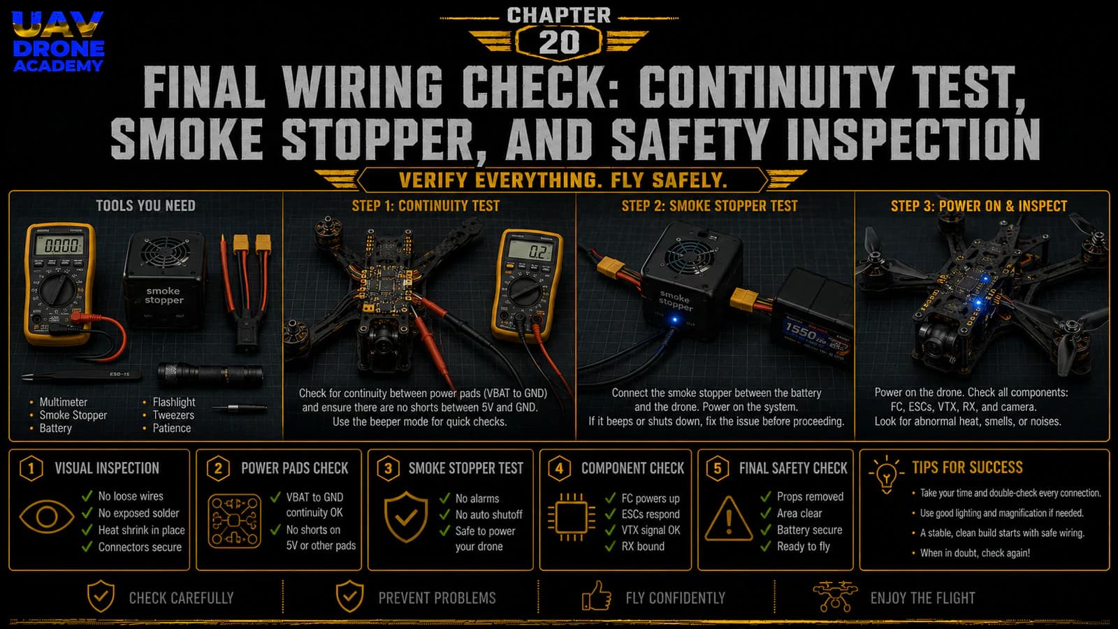
Step 17 — Continuity Test With Multimeter
Now we use the multimeter.
This is one of the most important checks in the entire build.
Set the multimeter to:
continuity mode
Continuity mode usually beeps when two points are electrically connected.
We use this to check whether battery positive and battery negative are accidentally shorted.
How to Test for a Short
Place one multimeter probe on:
- battery positive pad or XT60 positive side
Place the other probe on:
- battery negative pad or XT60 negative side
You are checking whether positive and negative are directly connected.
There should not be a direct short.
What Result Is Normal?
In many builds, the multimeter may beep very briefly because capacitors charge for a moment.
That short initial beep may be normal.
But a continuous beep usually means there may be a short circuit.
If you hear a continuous beep:
stop immediately
Do not connect a battery.
Inspect the build carefully.
What to Inspect If There Is a Short
If the multimeter indicates a short, check:
- battery pads
- solder bridges
- capacitor polarity
- motor pad bridges
- ESC components touching carbon
- loose strands of wire
- damaged insulation
- reversed polarity
- solder debris on the board
Do not power the drone until the short is found and fixed.
Step 18 — Check Voltage Pads If Possible
If you are experienced enough, you can also verify continuity around:
- 5V to GND
- 9V to GND
- VBAT to GND
Be careful.
Some readings may behave differently depending on the board design.
For beginners, the most critical check is still:
no direct short between battery positive and battery negative
Step 19 — Prepare the Smoke Stopper
A smoke stopper is a protection device used during first power-up.
It helps limit current if there is a short circuit.
This can protect:
- ESC
- flight controller
- VTX
- receiver
- camera
- other electronics
A smoke stopper does not replace the multimeter.
It adds another layer of protection.
Use both.
Step 20 — First Power Test With Smoke Stopper
Now prepare for the first protected power test.
Before connecting power, confirm:
- propellers are removed
- VTX antenna is installed
- multimeter check passed
- capacitor polarity is correct
- battery polarity is correct
- drone is on a safe surface
- no metal tools are touching the frame
- LiPo battery is in good condition
- smoke stopper is ready
Then connect:
battery → smoke stopper → drone
Do not connect the battery directly for the first test.
What to Watch During First Power-Up
During the first power test, watch carefully for:
- smoke
- sparks
- burning smell
- excessive heat
- strange sounds
- abnormal LEDs
- no power at all
- smoke stopper warning behavior
If anything seems wrong:
disconnect immediately
Do not wait.
A fast disconnect can prevent more damage.
What Normal Power-Up May Look Like
If everything is correct, you may see:
- flight controller LEDs
- receiver LED activity
- VTX LED activity
- ESC startup tones
- camera/VTX powering
- no smoke
- no burning smell
- no excessive heat
At this stage, we are not trying to configure anything yet.
We only want to confirm that the drone powers safely.
Step 21 — Check Component Temperature
After a short powered test, disconnect the battery.
Then carefully check whether any component became unusually hot.
Check:
- ESC
- flight controller
- VTX
- receiver
- camera
- voltage regulators
- capacitor
Some VTX units normally get warm, especially without airflow.
But components should not become dangerously hot within a few seconds.
If something becomes very hot quickly, investigate before continuing.
Step 22 — Connect to USB
After the first smoke stopper test, connect the flight controller to the computer using USB.
Do not connect the battery yet unless needed.
Check whether:
- the flight controller powers through USB
- the computer detects the board
- Betaflight Configurator can connect
- USB port remains accessible
- cable fits properly
This confirms that the flight controller is alive and communicating.
Step 23 — Do Not Configure Everything Yet
At this stage, avoid jumping too far ahead.
It is tempting to start changing Betaflight settings immediately.
But this chapter is focused on hardware safety.
Full Betaflight configuration will begin in the next part of the course.
For now, the goal is:
safe power and basic board recognition
That is enough.
Step 24 — Final Mechanical Check
After power testing, inspect the drone mechanically again.
Check:
- stack screws
- motor screws
- frame screws
- camera screws
- VTX mounting
- receiver mounting
- antenna mounting
- battery strap path
- top plate fitment
Make sure nothing shifted during wiring or testing.
Step 25 — Top Plate Test Fit
Now test fit the top plate again.
Do not force it.
Check that:
- no wires are crushed
- USB port remains accessible
- VTX is not pressed tightly
- antenna wires are not pinched
- battery strap path is clear
- capacitor has space
- top plate screws align correctly
If the top plate does not fit easily, fix the internal layout.
Do not simply compress the wires and hope for the best.
Step 26 — Final Pre-Configuration Status
At the end of this chapter, the drone should be:
- fully wired
- visually inspected
- mechanically inspected
- checked with a multimeter
- powered through a smoke stopper
- recognized by USB
- still without propellers
- ready for software configuration
This means the physical assembly phase is complete.
Common Beginner Mistakes
Skipping the Multimeter Test
This is one of the worst mistakes.
Never assume the wiring is correct.
Always test.
Powering Without a Smoke Stopper
The first power-up should be protected.
A smoke stopper can save expensive electronics.
Forgetting the VTX Antenna
Never power a VTX without an antenna connected.
Ignoring a Burning Smell
If something smells wrong, disconnect immediately.
Do not keep testing.
Assuming a Brief LED Flash Means Everything Is Fine
LEDs turning on does not guarantee wiring is perfect.
Continue inspecting.
Crushing Wires With the Top Plate
If the top plate does not fit cleanly, reorganize the wiring.
Do not force it.
Installing Propellers Too Early
This remains one of the most dangerous beginner mistakes.
No props until final flight preparation.
Beginner Safety Checklist
Before moving to software configuration, confirm:
- propellers removed
- battery polarity correct
- capacitor polarity correct
- no solder bridges
- no exposed copper touching carbon fiber
- no loose wires near propeller paths
- VTX antenna installed
- receiver antenna secured
- XT60 lead secured
- motor screws not touching windings
- multimeter continuity test passed
- smoke stopper test passed
- flight controller connects to USB
- top plate fits without crushing wires
If all points pass, the drone is ready for configuration.
What We Have Completed
At this stage, we have completed the full physical assembly of the drone.
We have:
- installed the frame
- installed motors
- soldered motor wires
- installed ESC and flight controller
- soldered battery lead
- installed capacitor
- wired FPV camera
- wired VTX
- wired ExpressLRS receiver
- checked continuity
- tested with smoke stopper
- confirmed basic USB connection
This closes the physical assembly part of the course.
Our Build Philosophy Moving Forward
Up to this point, our focus has been:
build cleanly and safely
From the next chapter onward, our focus changes to:
configure correctly and verify behavior
The drone is now physically built, but it is not ready to fly yet.
A drone is only truly flight-ready after:
- Betaflight configuration
- receiver setup
- motor direction verification
- failsafe setup
- OSD setup
- pre-flight inspection
- controlled testing
We are moving forward, but we are not rushing.
Conclusion
The final wiring check is one of the most important safety steps in building a 5-inch FPV drone.
This chapter protects the entire project from avoidable mistakes.
A careful inspection helps prevent:
- short circuits
- reversed polarity
- burned electronics
- VTX damage
- receiver problems
- wiring failures
- unsafe testing
For beginners, the key lesson is simple:
never power a drone blindly
Always inspect first.
Always test continuity.
Always use a smoke stopper during first power-up.
Always keep propellers removed during setup.
With the physical build now inspected and safely powered, we are ready to begin the software configuration phase.
In the next chapter, we will install Betaflight Configurator and connect the drone to the computer for the first time.
Next Chapter
Betaflight for Beginners: Installing and Connecting Your FPV Drone