Now that the frame is assembled, the motors are installed, and we understand the basics of FPV soldering, it is time to install one of the most important systems in the entire drone:
the ESC and flight controller stack
This is the electronic core of the build.
The ESC controls motor power.
The flight controller processes pilot commands, reads sensor data, stabilizes the drone, and coordinates the entire system.
Together, these two boards form what FPV pilots usually call:
the stack
Installing the stack correctly is extremely important because it affects:
- wiring organization
- soldering access
- vibration control
- USB access
- cooling
- reliability
- future maintenance
For beginners, this step may look intimidating at first.
But if we break it down slowly, it becomes a logical and manageable process.
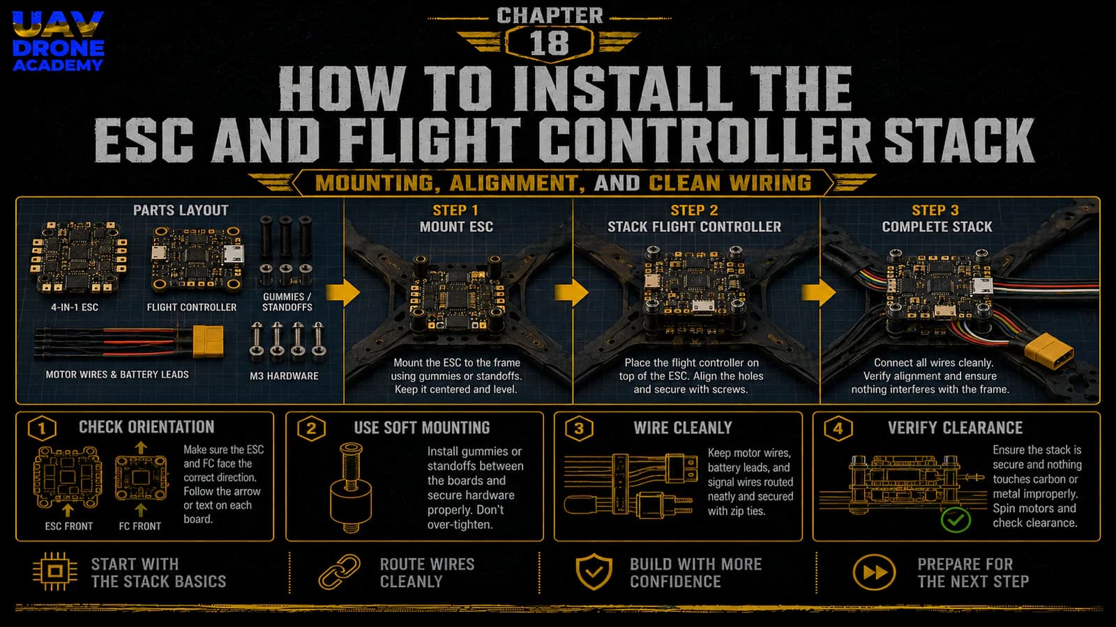
In this chapter, we will install the ESC and flight controller stack into the frame and prepare the build for wiring the main systems.
What Is the Stack?
In most modern 5-inch FPV drones, the stack is made of two main boards:
ESC Board
The ESC board controls the motors.
It receives battery power and distributes controlled power to each motor.
Flight Controller Board
The flight controller is the brain of the drone.
It receives commands from the receiver, reads sensor data, communicates with other components, and tells the ESC how fast each motor should spin.
These two boards are usually mounted vertically, one above the other, using stack screws and soft mounting gummies.
Why Stack Installation Matters
A poorly installed stack can create many problems.
These may include:
- vibration noise
- broken solder joints
- short circuits
- blocked USB port
- difficult maintenance
- overheating
- messy wiring
- unreliable flight behavior
A clean stack installation makes the rest of the build much easier.
The goal is not simply to “fit the boards inside the frame.”
The goal is to install them in a way that supports a clean, reliable, repairable FPV build.
Before You Start
Before installing the stack, prepare:
- frame with motors installed
- ESC board
- flight controller board
- stack screws
- soft mounting gummies
- nylon nuts or metal nuts
- hex driver
- tweezers
- wiring harness between ESC and FC
- multimeter
- battery lead
- capacitor
- soldering tools
Do not connect a battery yet.
At this stage, we are only installing and preparing the electronics.
Step 1 — Identify the ESC and Flight Controller
Before mounting anything, identify both boards clearly.
The ESC usually has:
- large battery pads
- motor pads
- current rating markings
- large power traces
- connector port for the flight controller harness
The flight controller usually has:
- USB port
- gyro chip
- small solder pads
- UART pads
- receiver pads
- VTX/camera pads
- boot button
- connector port for ESC harness
Do not assume both boards can be mounted in any direction without checking documentation.
Always identify:
- front direction
- USB position
- pad labels
- connector orientation
- arrow markings
- wiring harness position
Step 2 — Understand Board Orientation
Most flight controllers have an arrow printed on the board.
This arrow usually indicates the forward direction.
Ideally, the arrow should point toward the front of the drone.
This makes configuration simpler later.
However, some builds mount the flight controller rotated because of USB access or wiring needs.
Betaflight can compensate for board rotation later.
But for beginners, the simplest option is:
mount the flight controller facing forward if possible
This reduces confusion during setup.
Step 3 — Plan USB Access
Before installing the flight controller, check where the USB port will be.
This is very important.
Later, you will need to connect the drone to Betaflight Configurator.
If the USB port is blocked by:
- frame plates
- standoffs
- wires
- camera plates
- VTX
configuration becomes frustrating.
Before tightening anything, test whether you can reach the USB port with a cable.
Also make sure your cable is a data-capable USB cable, not a charge-only cable.
Step 4 — Check Stack Mounting Size
Most beginner-friendly 5-inch builds use:
30x30 mm stack mounting
Make sure your frame mounting holes match your stack.
The stack screws should pass cleanly through:
- frame
- ESC
- soft mounts
- flight controller
- nuts
Do not force screws through misaligned holes.
If something does not fit, stop and check the mounting pattern.
Step 5 — Install the Stack Screws
Start by installing the stack screws through the frame’s mounting holes.
Depending on the frame, these screws may go:
- from the bottom upward
- from the top downward
For many builds, screws pass upward from the bottom plate.
Install them carefully and make sure they are straight.
The screws form the vertical posts that hold the ESC and flight controller.
Step 6 — Add Soft Mounting
Soft mounting is important because the flight controller contains sensitive sensors.
The gyro can detect vibration.
Too much mechanical vibration can create noisy sensor data and poor flight performance.
Soft mounting gummies help isolate the flight controller from frame vibration.
Most modern stacks include rubber gummies or soft mounts.
Install them according to the stack design.
The boards should be supported firmly, but not crushed.
Step 7 — Mount the ESC First
In most 5-inch builds, the ESC board is mounted at the bottom of the stack.
This makes sense because:
- it connects directly to motor wires
- it connects directly to the battery lead
- it handles high current
- it benefits from a lower central position
Place the ESC onto the stack screws with correct orientation.
Make sure:
- motor pads are accessible
- battery pads are accessible
- the ESC connector is reachable
- the board is not touching carbon fiber
- there is space for the capacitor
- motor wires can reach the pads cleanly
Step 8 — Check ESC Clearance
The ESC must not touch the carbon fiber frame directly.
Carbon fiber is conductive enough to cause electrical problems.
Make sure there is clearance between:
- ESC components
- solder joints
- frame plates
- screws
- carbon fiber edges
If the ESC touches carbon fiber, it can create a short circuit.
This is one of the reasons soft mounting and correct spacing matter so much.
Step 9 — Plan Motor Wire Routing to the ESC
Before soldering, route the motor wires visually toward the ESC pads.
Each motor has three wires.
The wires should reach the ESC motor pads without:
- excessive tension
- sharp bends
- crossing over the flight controller
- entering propeller paths
Do not cut the motor wires too short.
For beginners, it is better to leave slightly more length than needed.
A little extra wire can be managed.
A wire that is too short creates real problems.
Step 10 — Solder Motor Wires to the ESC
Once you are confident in the routing, solder the motor wires to the ESC motor pads.
For each motor:
- tin the pads
- tin the wires
- apply flux
- solder cleanly
- inspect the joints
At this stage, the order of the three motor wires is usually not critical.
Motor direction can be changed later in software.
What matters now is:
- clean solder joints
- no solder bridges
- no loose strands
- no excessive exposed wire
- good mechanical connection
Step 11 — Solder the Battery Lead
The battery lead connects the battery to the ESC.
Most 5-inch FPV drones use:
XT60 connector
The XT60 lead will usually be soldered to the large positive and negative pads on the ESC.
This is one of the most important soldering jobs in the entire build.
Important Battery Lead Rules
Always confirm polarity before soldering:
- positive wire to positive pad
- negative wire to negative pad
Reversed polarity can destroy electronics instantly.
The battery lead should be routed so that:
- it does not touch propellers
- it does not pull on solder pads
- it can connect to the battery easily
- it has strain relief
- it stays secure during crashes
Step 12 — Solder the Capacitor
Most FPV stacks include a capacitor.
The capacitor helps reduce voltage spikes and electrical noise.
It is usually soldered to the battery pads:
- positive leg to positive pad
- negative leg to negative pad
Capacitor polarity matters.
The negative side is usually marked with a stripe.
Why the Capacitor Matters
The capacitor helps protect the electronics from:
- voltage spikes
- electrical noise
- unstable power behavior
For a 5-inch 6S build, installing the capacitor is strongly recommended.
It is a small part that can improve system reliability significantly.
Step 13 — Secure the Capacitor
After soldering, the capacitor should be secured.
Do not leave it hanging freely.
You can secure it with:
- heat shrink
- zip tie
- double-sided tape
- frame-mounted position
Make sure the capacitor:
- cannot hit propellers
- cannot vibrate excessively
- cannot stress the solder pads
- does not block the top plate
- does not interfere with the battery strap
Step 14 — Inspect the ESC Soldering
Before adding the flight controller, inspect all ESC solder joints carefully.
Check:
- motor pads
- battery pads
- capacitor soldering
- polarity
- loose strands
- solder bridges
- melted insulation
- wire tension
Use a magnifying glass or phone camera if needed.
This inspection matters a lot.
Fix problems now, before the build becomes more crowded.
Step 15 — Use the Multimeter
Before connecting the flight controller or battery, use the multimeter.
Check continuity between:
- battery positive
- battery negative
There should not be a direct short.
If the multimeter beeps continuously between positive and negative, stop immediately and inspect the board.
Do not connect a battery until the issue is solved.
Step 16 — Mount the Flight Controller
Once the ESC wiring looks clean, mount the flight controller above the ESC.
Make sure:
- the arrow points forward if possible
- the USB port is accessible
- the board is soft mounted
- the board is not crushed by nuts
- the FC does not touch solder joints below it
- there is enough space between boards
Do not overtighten the flight controller.
The soft mounts should reduce vibration, not be compressed completely.
Step 17 — Connect the ESC-to-FC Harness
Most modern stacks include a wiring harness between the ESC and flight controller.
This harness usually carries:
- battery voltage
- ground
- current sensor signal
- motor signal wires
- telemetry signal
Connect the harness carefully.
Make sure:
- the connector is fully seated
- orientation is correct
- wires are not pinched
- the harness does not pull tightly
- the harness does not touch sharp carbon edges
Never force a connector.
If it does not fit, check orientation.
Step 18 — Confirm Board Spacing
After installing the flight controller, check the vertical spacing.
Make sure:
- the FC does not touch ESC components
- solder joints are not pressed against the FC
- the harness has room
- the top plate can still fit
- USB access remains possible
This is a good moment to test fit the top plate again.
Do not fully close the frame yet.
There are still more components to install.
Step 19 — Think About Future Wiring
The flight controller will later connect to:
- receiver
- FPV camera
- VTX
- possibly buzzer
- possibly GPS
- other accessories later
Before moving forward, look at the pads and identify where wires will go.
Try to avoid blocking important pads with:
- battery lead
- capacitor
- motor wires
- zip ties
- VTX placement
Good planning now makes the next chapter much easier.
Step 20 — First Power Test Preparation
After the ESC and FC are installed, we are close to the first basic power test.
But before connecting a battery, check:
- no propellers installed
- no visible solder bridges
- battery polarity correct
- capacitor polarity correct
- multimeter shows no short
- smoke stopper available
- drone is on a safe surface
- no loose metal tools near the frame
The first power test should always be done carefully.
Important Safety Reminder
At this stage:
do not install propellers
This rule remains critical.
Propellers should stay off during:
- soldering
- power testing
- Betaflight setup
- motor testing
- receiver setup
- failsafe setup
Only install propellers when the drone is fully configured and ready for controlled flight testing.
Common Beginner Mistakes
Mounting the Flight Controller Backwards
This can be corrected in Betaflight, but it creates confusion for beginners.
If possible, mount the arrow forward.
Blocking the USB Port
Always check USB access before finalizing the stack.
Overtightening Soft Mounts
Soft mounts should reduce vibration.
If crushed too tightly, they lose effectiveness.
Letting the ESC Touch Carbon Fiber
Carbon fiber can cause electrical issues.
Maintain proper clearance.
Reversing Battery Polarity
This is one of the most destructive mistakes.
Always confirm positive and negative before soldering.
Forgetting the Capacitor
The capacitor helps protect the electronics.
Install it cleanly and secure it properly.
Skipping the Multimeter Check
Never power the drone without checking for shorts first.
Beginner Build Tip
After soldering the ESC and installing the stack, take clear close-up photos of:
- battery pads
- capacitor connection
- motor solder joints
- ESC-to-FC harness
- board spacing
- USB access
Photos make inspection easier.
Zooming in often reveals mistakes that are hard to see directly.
What We Have Completed
At this stage, we have:
- identified the ESC and flight controller
- planned board orientation
- checked USB access
- mounted the ESC
- soldered motor wires
- soldered the XT60 battery lead
- soldered and secured the capacitor
- checked for shorts
- mounted the flight controller
- connected the ESC-to-FC harness
- verified stack spacing
This is a major milestone.
The drone now has its main electronic core installed.
Our Build Philosophy Moving Forward
The deeper we move into the build, the more important clean work becomes.
A clean stack installation creates:
- easier wiring
- easier troubleshooting
- better reliability
- safer power testing
- simpler future repairs
Remember:
reliability is built step by step
Every clean solder joint, every properly routed wire, and every careful inspection reduces the chance of problems later.
Conclusion
Installing the ESC and flight controller stack is one of the most important steps in building a 5-inch FPV drone.
This system controls:
- power delivery
- motor response
- stabilization
- communication
- overall flight behavior
For beginners, the key is not speed.
The key is:
- correct orientation
- clean soldering
- safe spacing
- proper wire routing
- careful inspection
With the ESC and flight controller installed, the drone now has its electronic core in place.
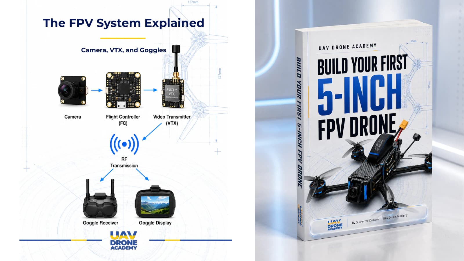
Next, we will connect the systems that allow the drone to see and communicate:
the FPV camera, VTX, and ExpressLRS receiver.
Next Chapter
How to Wire the FPV Camera, VTX, and Receiver