Now that the frame is assembled, it is time to install the motors.
This is an exciting step because the drone starts to look much closer to a real FPV aircraft.
The motors are responsible for spinning the propellers and generating thrust. Without them, the drone is only a carbon fiber structure with electronics.
But motor installation is not just about screwing four motors onto the arms.
A clean motor installation affects:
- reliability
- vibration
- wire routing
- repairability
- ESC soldering
- motor direction setup
- overall build quality
For beginners, this step is very important because a few small mistakes can create problems later.
In this chapter, we will install the motors carefully and prepare the drone for the next major step: soldering.
What the Motors Do
The motors are part of the drone’s power and propulsion system.
Their job is simple:
spin the propellers
When the motors spin the propellers, the propellers push air downward and generate thrust.
This thrust allows the drone to:
- lift off
- hover
- accelerate
- turn
- stabilize itself
- perform maneuvers
Each motor is controlled independently by the ESC.
That independent motor control is what allows the flight controller to stabilize and move the drone.
Before Installing the Motors
Before attaching anything to the frame, prepare:
- four brushless motors
- correct motor screws
- metric hex driver
- frame with arms installed
- small parts tray
- threadlocker, optional
- wire cutters, optional
- zip ties, optional
Do not install propellers yet.
This is extremely important.
Never install propellers during the build process.
Propellers should only be installed much later, after:
- soldering
- Betaflight setup
- motor direction checks
- failsafe setup
- final safety inspection
For now, motors only.
No props.
Step 1 — Identify the Motors
A 5-inch FPV drone uses four motors.
Usually, all four motors are identical.
Each motor has:
- motor bell
- motor base
- shaft
- mounting holes
- three motor wires
The three motor wires will later be soldered to the ESC.
At this stage, we only need to mount the motors to the frame arms.
Step 2 — Check Motor Mounting Pattern
Most 5-inch FPV motors use a standard mounting pattern.
Common motor mounting patterns include:
- 16x16 mm
- 19x19 mm
Most modern 5-inch frames support these patterns.
Before using screws, place the motor on the arm and check:
- hole alignment
- motor position
- wire direction
- screw clearance
The motor should sit flat on the carbon fiber arm.
If it does not sit flat, stop and check the mounting pattern.
Step 3 — Understand Motor Wire Direction
Before tightening the motors, decide where the motor wires should point.
Usually, motor wires should face toward the center of the frame.
This makes it easier to route them to the ESC later.
A clean layout usually looks like this:
- front motor wires point backward toward the stack
- rear motor wires point forward toward the stack
- all wires route cleanly along the arms
- wires stay away from propeller paths
This creates a simple, organized build.
Why Wire Direction Matters
Motor wire direction affects:
- soldering difficulty
- wire length
- repairability
- propeller clearance
- build cleanliness
If the motor wires point outward or in a strange direction, you may need to bend them sharply or use longer wire paths.
That can make the build messy and harder to maintain.
A few seconds of planning now makes the next steps much easier.
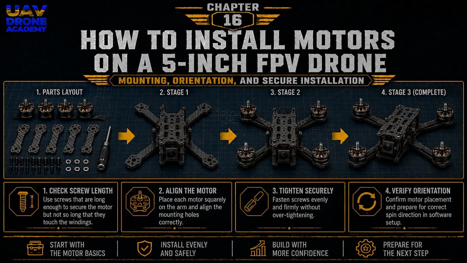
Step 4 — Choose the Correct Motor Screws
This is one of the most important details in motor installation.
Motors are installed using small screws that pass through the carbon fiber arm and into the motor base.
The screw must be long enough to hold the motor securely.
But it must not be too long.
Screws that are too long can damage the motor windings.
This is a very common beginner mistake.
Why Screw Length Is Critical
Inside the motor, there are copper windings.
If the screw enters too deeply, it can touch or cut those windings.
This can cause:
- short circuits
- motor failure
- ESC damage
- smoke on first power-up
- unstable behavior
Always check screw length carefully.
Step 5 — Test Screw Length Before Final Installation
Before tightening the motor, insert one screw through the arm and check how far it extends.
The screw should enter the motor base securely, but it should not reach the internal windings.
If the frame arm is thick, you may need slightly longer screws.
If the arm is thinner, you may need shorter screws.
Do not assume the screws included with the motors are automatically correct for your frame.
Always verify.
Step 6 — Mount the First Motor
Place the first motor on one arm.
Align the motor holes with the frame holes.
Insert the screws by hand first.
This helps avoid cross-threading.
Once all screws are started, tighten them gradually.
Do not fully tighten one screw immediately.
Instead:
- start all screws
- lightly tighten each one
- confirm the motor is centered
- then tighten gradually in a cross pattern
The motor should sit flat and secure.
Step 7 — Do Not Overtighten
Motor screws should be secure, but not excessively tight.
Overtightening can:
- strip screw heads
- damage threads
- stress the motor base
- damage the carbon arm
Use firm pressure, not excessive force.
If using threadlocker, use only a tiny amount and only on metal-to-metal screw contact.
Avoid getting threadlocker on carbon fiber, plastic, or electronics.
Step 8 — Repeat for the Other Motors
Install the remaining three motors using the same process.
For each motor, check:
- correct screw length
- wire direction
- flat contact with the arm
- secure mounting
- no loose hardware
At the end, all four motors should be installed symmetrically.
Step 9 — Check Motor Bell Clearance
After installing each motor, spin the motor bell gently by hand.
It should rotate freely.
There should be:
- no scraping
- no grinding
- no screw contact
- no unusual resistance
If the motor does not spin freely, stop and inspect immediately.
Possible causes:
- screws too long
- motor damaged
- debris inside motor
- misalignment
Do not continue until the motor spins cleanly.
Step 10 — Route the Motor Wires Along the Arms
Once the motors are installed, gently route the motor wires along each arm toward the center of the frame.
Do not cut the wires yet unless you are ready to solder.
For now, just plan the route.
Good motor wire routing should:
- follow the arms cleanly
- stay away from propeller paths
- avoid sharp bends
- reach the ESC pads comfortably
- leave enough slack for repairs
Should You Shorten Motor Wires?
Eventually, motor wires may be shortened for a cleaner build.
But beginners should be careful.
If you cut wires too short, you may make soldering difficult or create problems during future repairs.
A good beginner rule is:
leave a little extra length
A slightly longer wire is better than a wire that cannot reach the ESC comfortably.
Step 11 — Protect the Motor Wires
Motor wires run along the arms, which means they are exposed during crashes.
Later, we may secure them using:
- zip ties
- electrical tape
- fabric tape
- heat shrink
- 3D printed wire protectors
The goal is to keep wires:
- stable
- away from propellers
- protected from impact
- easy to inspect
Do not permanently lock everything down yet.
We still need to solder the wires to the ESC.
Step 12 — Understand Motor Numbering
Motor numbering will matter later in Betaflight.
For now, you do not need to memorize everything perfectly.
But it is useful to understand that Betaflight expects each motor to respond in a specific position.
A common Betaflight motor order is:
- motor 1: rear right
- motor 2: front right
- motor 3: rear left
- motor 4: front left
This will be verified later in Betaflight.
Do not worry if this feels abstract now.
We will check motor order during configuration.
Step 13 — Motor Direction Comes Later
Another important point:
motor direction is not finalized during physical installation
Brushless motors can spin either direction depending on ESC configuration.
Later, we will set motor direction using software.
For now, focus on:
- secure mounting
- correct wire routing
- clean installation
Motor direction will be handled in Betaflight or ESC configuration later.
Step 14 — Never Install Propellers Yet
This point is worth repeating.
At this stage:
do not install propellers
Propellers should remain off during:
- soldering
- Betaflight connection
- motor testing
- receiver setup
- failsafe setup
- first power checks
Motors can spin unexpectedly during setup.
Without propellers, that is usually harmless.
With propellers, it can become dangerous.
Step 15 — Inspect the Full Motor Installation
After all four motors are installed, inspect the drone from all sides.
Check:
Top View
Are all motors aligned symmetrically?
Side View
Are all motors sitting flat on the arms?
Bottom View
Are screws properly seated?
Wire Routing
Do the wires point toward the center cleanly?
Motor Bells
Do all motors spin freely by hand?
This inspection prevents small mistakes from becoming larger problems later.
Common Beginner Mistakes
Using Screws That Are Too Long
This is one of the most dangerous beginner mistakes.
Long screws can damage the motor windings and create electrical problems.
Always check screw length.
Pointing Motor Wires in the Wrong Direction
Poor wire direction can make the build messy and difficult to solder.
Plan wire routing before tightening motors.
Cutting Motor Wires Too Short
Short wires make soldering harder and reduce repair flexibility.
Leave enough length for comfortable routing.
Installing Propellers Too Early
Never install propellers during setup or testing.
Props should only be installed near the final flight preparation stage.
Forgetting to Check Motor Bell Movement
Always spin each motor by hand after installation.
The bell should rotate freely without scraping.
Beginner Build Tip
Take a photo of the drone after motor installation.
This helps you compare progress later and makes troubleshooting easier.
If you ask for help in an FPV community, clear photos of:
- motor mounting
- screw placement
- wire routing
can make it much easier for others to identify problems.
What We Have Completed
At this stage, we have:
- identified all four motors
- checked the mounting pattern
- selected correct screws
- mounted each motor
- checked screw length
- verified motor bell clearance
- planned motor wire routing
- prepared the build for soldering
The drone now has its propulsion hardware physically installed.
The next step is learning how to solder correctly.
Our Build Philosophy Moving Forward
As we continue the assembly, the most important principle is:
clean work prevents future problems
A clean motor installation makes the next steps easier:
- ESC installation
- soldering
- wire routing
- motor testing
- Betaflight configuration
Do not rush.
FPV rewards careful building.
Conclusion
Installing motors on a 5-inch FPV drone is a simple step, but it must be done carefully.
The most important points are:
- use the correct screw length
- point motor wires toward the center
- avoid overtightening
- check that every motor spins freely
- never install propellers during setup
With the motors installed properly, our drone is now ready for one of the most important technical skills in FPV building:
soldering.
In the next chapter, we will learn the fundamentals of FPV soldering and understand how to create clean, reliable electrical connections.
Next Chapter
FPV Soldering Guide for Beginners: Tools, Technique, and Safety