At this stage of the build, the drone already has its main structure and electronic core installed.
We have:
- assembled the frame
- installed the motors
- learned the basics of FPV soldering
- installed the ESC
- mounted the flight controller
- connected the ESC-to-FC harness
- soldered the battery lead
- installed the capacitor
Now it is time to connect the systems that allow the drone to:
- see
- transmit video
- receive pilot commands
- communicate with the radio controller
In this chapter, we will wire three important components:
FPV camera
VTX
ExpressLRS receiver
These components are smaller than motors or batteries, but they are essential.
Without the FPV camera and VTX, the pilot cannot see.
Without the receiver, the pilot cannot control the drone.
So even though this step involves small wires, it is one of the most important parts of the build.
The Goal of This Chapter
The goal is not just to solder wires randomly.
The goal is to understand how each signal travels through the drone.
By the end of this chapter, you should understand:
- how the camera sends video to the flight controller
- how the flight controller sends video to the VTX
- how the VTX sends video to the goggles
- how the receiver sends pilot commands to the flight controller
- why correct voltage matters
- why ground connections matter
- how to keep wiring clean and reliable
This is where the drone starts becoming a complete FPV system.
Before You Start
Before wiring anything, prepare:
- FPV camera
- analog VTX
- ExpressLRS receiver
- flight controller wiring diagram
- soldering iron
- solder
- flux
- wire cutters
- wire strippers
- tweezers
- heat shrink tubing
- zip ties
- double-sided tape
- multimeter
- smoke stopper
Also make sure:
propellers are not installed
This rule remains extremely important.
Never install propellers during wiring, soldering, testing, Betaflight setup, or receiver configuration.
Read the Flight Controller Diagram First
Every flight controller is slightly different.
Before soldering, always check the wiring diagram for your exact board.
You need to identify pads for:
- 5V
- 9V or VBAT
- GND
- camera video input
- video output to VTX
- UART TX
- UART RX
- receiver pads
- VTX control pad
- SmartAudio or IRC Tramp pad
Do not guess.
Pad labels matter.
A wrong connection can damage a component.
Understanding Voltage Pads
This is one of the most important beginner concepts.
Different components need different voltage.
Common flight controller power pads include:
5V
Used for:
- receivers
- some cameras
- some accessories
9V
Often used for:
- VTX
- FPV cameras
- video systems that benefit from cleaner regulated power
VBAT
Direct battery voltage.
Used only by components designed to accept full battery voltage.
On a 6S drone, VBAT can be up to 25.2V when fully charged.
Do not connect a 5V component to VBAT.
That can destroy it instantly.
Ground Is Just as Important as Power
Every powered component needs:
- positive voltage
- ground
Ground is the electrical reference point for the circuit.
A poor ground connection can cause:
- noisy video
- unreliable receiver behavior
- random signal problems
- unstable component operation
For clean wiring, try to use ground pads close to the related signal and power pads when possible.
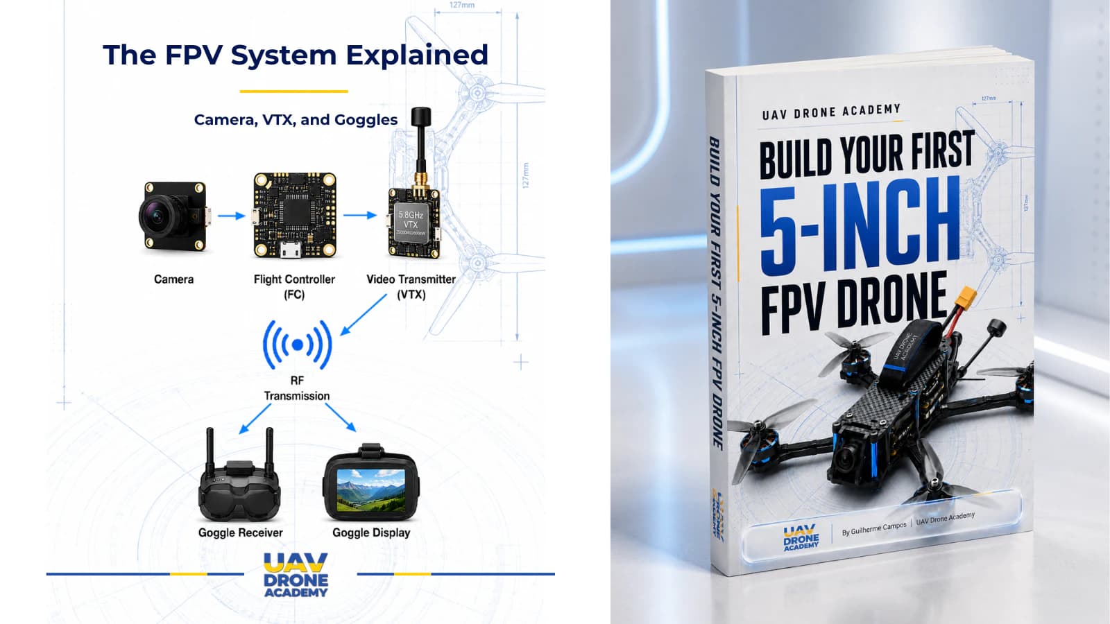
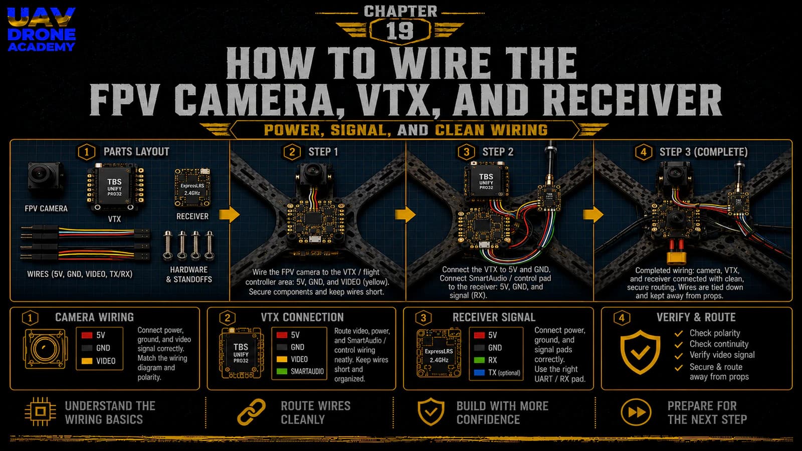
Part 1 — Wiring the FPV Camera
The FPV camera captures the live image from the drone’s perspective.
In a typical analog FPV build, the camera connects to the flight controller first.
This allows the flight controller to add OSD information to the video.
OSD means:
On-Screen Display
The OSD can show useful information in your goggles, such as:
- battery voltage
- timer
- flight mode
- warnings
- signal information
- other flight data
FPV Camera Wires
Most analog FPV cameras have three basic wires:
- power
- ground
- video signal
Some cameras may include extra wires for camera control, but beginners usually only need the basic three.
Camera Power
Many modern FPV cameras can run on 5V or 9V, depending on the model.
Always check the camera specifications.
For our beginner build, a common approach is:
camera power to 5V or 9V regulated pad
Do not connect the camera to VBAT unless the camera specifically supports battery voltage.
Camera Ground
The camera ground wire connects to a GND pad on the flight controller.
Ideally, use a ground pad close to the camera power and video pads.
This keeps wiring cleaner and may reduce video noise.
Camera Video Signal
The camera video signal wire connects to the flight controller’s:
CAM pad
or:
Video In pad
This sends raw camera video into the flight controller.
The flight controller then overlays OSD information onto the video feed.
Basic Camera Wiring Logic
The basic camera wiring looks like this:
- camera power → 5V or 9V pad
- camera ground → GND pad
- camera video → CAM / Video In pad
This sends live video from the camera into the flight controller.
Mounting the FPV Camera
Before final soldering, test fit the camera in the frame.
Check:
- lens clearance
- side plate fitment
- camera angle adjustment
- screw length
- cable routing
- protection from crashes
Do not overtighten camera screws.
The camera should be secure, but still adjustable if needed.
For beginners, a moderate camera angle is better than an extreme angle.
A very high camera angle makes the drone fly faster to maintain a normal forward view.
Part 2 — Wiring the VTX
The VTX transmits the video signal from the drone to your goggles.
In an analog FPV build, the video signal path usually goes:
camera → flight controller → VTX → goggles
This allows the flight controller to add OSD information before the video reaches the VTX.
VTX Wires
Most analog VTX units require:
- power
- ground
- video signal
- control wire
The control wire may use:
- SmartAudio
- IRC Tramp
- another VTX control protocol
This allows Betaflight to control VTX settings.
VTX Power
Many VTX units can accept 7V–36V or similar wide voltage ranges.
Others require 5V or 9V.
Always check the VTX specifications.
For our beginner build, a good approach is usually:
VTX power to 9V regulated pad
Why?
Because a regulated 9V pad often provides cleaner power than raw battery voltage.
Cleaner power can help reduce video noise.
But again:
always follow your specific VTX specifications
VTX Ground
The VTX ground wire connects to GND.
Use a ground pad near the VTX power and video output pad if available.
Good grounding helps maintain stable video signal quality.
VTX Video Signal
The VTX video wire connects to the flight controller’s:
VTX pad
or:
Video Out pad
This sends OSD-processed video from the flight controller to the VTX.
VTX Control Wire
The VTX control wire connects to a flight controller pad that supports VTX control.
This is often a:
TX pad on a UART
or a specific pad labeled:
- SA
- SmartAudio
- Tramp
- VTX CTRL
This wire allows Betaflight to change:
- VTX band
- VTX channel
- VTX power level
- pit mode
For beginners, this is very useful because it avoids changing VTX settings manually with tiny buttons.
Basic VTX Wiring Logic
The basic VTX wiring looks like this:
- VTX power → 9V or appropriate voltage pad
- VTX ground → GND pad
- VTX video → VTX / Video Out pad
- VTX control → SmartAudio / Tramp / UART TX pad
This completes the video output path.
Install the VTX Antenna Before Powering
This is extremely important.
Never power a VTX without an antenna installed.
A VTX can overheat or damage itself if powered without an antenna.
Before any power test, make sure:
- the antenna is connected
- the connector is secure
- the antenna is mounted safely
- the antenna is not touching propeller paths
VTX Heat Warning
VTX units can become very hot on the bench.
This happens because there is no airflow when the drone is sitting still.
During configuration:
- avoid leaving the drone powered for too long
- use low VTX power when possible
- use pit mode if available
- place a small fan nearby if needed
Do not ignore VTX heat.
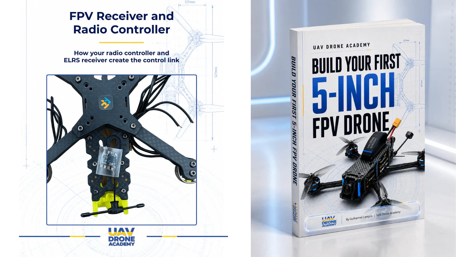
Part 3 — Wiring the ExpressLRS Receiver
The receiver allows the drone to receive commands from the radio controller.
For our beginner build, we are using:
2.4GHz ExpressLRS
The receiver sends pilot commands to the flight controller using a digital communication protocol.
Most ELRS receivers use:
CRSF protocol
This requires a UART connection.
Receiver Wires
Most ELRS receivers require:
- 5V
- GND
- TX
- RX
Some receivers may include extra pads, but these four are the most important.
Receiver Power
Most ELRS receivers use:
5V
Connect receiver power to a 5V pad on the flight controller.
Do not connect a 5V receiver to VBAT.
That can destroy it.
Receiver Ground
Connect receiver ground to a GND pad.
Use a clean, nearby ground pad if available.
Receiver TX and RX
This is where beginners often get confused.
UART communication uses TX and RX.
TX means transmit.
RX means receive.
The important rule is:
TX goes to RX
RX goes to TX
So for the receiver:
- receiver TX → flight controller RX pad
- receiver RX → flight controller TX pad
This crossed connection allows both devices to communicate.
Basic ELRS Receiver Wiring Logic
The basic receiver wiring looks like this:
- receiver 5V → flight controller 5V
- receiver GND → flight controller GND
- receiver TX → flight controller RX
- receiver RX → flight controller TX
Later in Betaflight, we will enable Serial RX on the correct UART.
Choosing the Correct UART
A UART is a communication port on the flight controller.
Your receiver must be connected to one available UART.
For example:
- receiver TX to RX2
- receiver RX to TX2
Then, in Betaflight, you will enable Serial RX on UART2.
The physical wiring and software configuration must match.
If you wire the receiver to UART2 but enable Serial RX on UART1, the receiver will not work correctly.
Receiver Antenna Placement
ELRS receiver antenna placement matters.
Good antenna placement helps:
- signal reliability
- range
- link quality
- failsafe resistance
Avoid placing the antenna:
- inside carbon fiber
- directly under the battery
- next to high-current wires
- touching the frame
- near the VTX antenna if possible
For 2.4GHz ELRS, the antenna should have a clear position away from major interference sources.
Mounting the Receiver
Receivers are usually mounted using:
- double-sided tape
- heat shrink
- zip ties
- small 3D printed mount
The receiver should be secure but not crushed.
Make sure the wires:
- are not under tension
- are not rubbing sharp carbon edges
- do not interfere with the top plate
- are easy to inspect later
Wire Routing Principles
At this stage, the drone may start looking crowded.
Good wire routing is extremely important.
Try to keep:
Power Wires Separate When Possible
High-current wires can introduce electrical noise.
Signal Wires Short and Clean
Avoid unnecessary loops.
Wires Away From Props
Any loose wire can be destroyed by propellers.
Wires Away From Sharp Carbon Edges
Carbon edges can cut insulation over time.
USB Port Accessible
Do not block the flight controller USB port.
Top Plate Fitment Clear
Before finalizing wires, test fit the top plate.
Do Not Permanently Lock Everything Yet
Even after soldering, avoid fully finalizing all wire management immediately.
Why?
Because we still need to:
- test power
- connect to Betaflight
- verify receiver communication
- verify video signal
- check OSD
- confirm motor behavior
- inspect for heat
Use temporary wire management first.
Once everything works, final cleanup becomes easier.
Inspection Before Power
Before connecting a battery, inspect every connection carefully.
Check the camera:
- power connected to correct voltage
- ground connected correctly
- video connected to CAM / Video In
Check the VTX:
- antenna installed
- power connected to correct voltage
- ground connected correctly
- video connected to VTX / Video Out
- control wire connected correctly
Check the receiver:
- 5V connected correctly
- GND connected correctly
- TX/RX crossed correctly
- antenna placed properly
Also check:
- no solder bridges
- no loose strands
- no exposed wires touching carbon
- no wires near propeller paths
- top plate does not crush wires
Multimeter Check
Before powering the drone, use the multimeter again.
Check continuity between:
- battery positive
- battery negative
There should not be a direct short.
If there is a short, do not connect the battery.
Inspect and fix the issue first.
First Power Test With Smoke Stopper
The first power test after wiring should be done with a:
smoke stopper
Before powering:
- remove propellers
- connect VTX antenna
- place the drone on a safe surface
- connect smoke stopper
- then connect battery
Watch for:
- smoke
- burning smell
- excessive heat
- abnormal sounds
- unusual LED behavior
If something seems wrong, disconnect immediately.
What Should Happen During First Power
If everything is wired correctly, you may see:
- flight controller LEDs
- receiver LEDs
- VTX LEDs
- camera/VTX powering
- normal ESC startup tones
Do not worry if some systems still need configuration.
At this stage, the goal is only to confirm that nothing immediately fails electrically.
Common Beginner Mistakes
Connecting Components to the Wrong Voltage
This can destroy components instantly.
Always check whether the component needs 5V, 9V, or VBAT.
Wiring TX to TX and RX to RX
For UART devices, remember:
TX goes to RX
RX goes to TX
This is a very common beginner mistake.
Forgetting the VTX Antenna
Never power a VTX without an antenna.
Blocking the USB Port
You will need USB access for Betaflight.
Do not bury the port behind wires or components.
Overheating the VTX on the Bench
Do not leave the drone powered on for long periods without airflow.
Making Wires Too Short
Short wires make repairs harder.
Leave enough length for comfortable routing.
Leaving Loose Wires Near Props
Loose wires can be cut instantly by propellers.
Secure wiring before flight.
Beginner Build Tip
Use a simple wiring diagram or photo for your exact flight controller.
Before soldering each wire, say the connection out loud:
- camera power to 5V
- camera ground to GND
- camera video to CAM
- VTX video to VTX
- receiver TX to flight controller RX
- receiver RX to flight controller TX
This simple habit reduces wiring mistakes.
What We Have Completed
At this point, we have wired:
- FPV camera
- analog VTX
- VTX antenna
- ExpressLRS receiver
- receiver antenna
- video signal path
- radio control signal path
The drone now has:
- propulsion hardware
- main electronics
- video system
- control receiver
- basic wiring needed for configuration
This is a major step.
Our Build Philosophy Moving Forward
The drone is becoming more complete, but this is also where careful work matters most.
Remember:
small wiring mistakes can create big problems
A clean build is easier to:
- inspect
- configure
- repair
- troubleshoot
- upgrade
Do not rush this stage.
Every wire should have a reason and a clean path.
Conclusion
Wiring the FPV camera, VTX, and receiver turns the drone into a functional FPV platform.
The camera gives the drone vision.
The VTX sends that vision to the pilot.
The receiver connects the pilot’s radio controller to the flight controller.
Together, these systems allow real FPV flight to happen.
For beginners, the most important concepts are:
- use the correct voltage
- connect grounds properly
- understand video in and video out
- cross TX and RX for UART devices
- install the VTX antenna before powering
- inspect everything before connecting a battery
With these systems wired, the drone is now ready for one of the most important safety steps in the entire build:
the final wiring check.
Next Chapter
Final Wiring Check: Continuity Test, Smoke Stopper, and Safety Inspection