Accessories, Communication Systems, Flight Control
Technical Tutorial: Installation and Configuration of the FCAT V 1.0
The FCAT V 1.0 is an autonomous initiation system. Since it features its own internal battery, it operates independently from the drone’s propulsion system, ensuring detonation even if the UAV’s main battery is ejected or destroyed upon impact.
1. Hardware Integration (Signal Mapping)
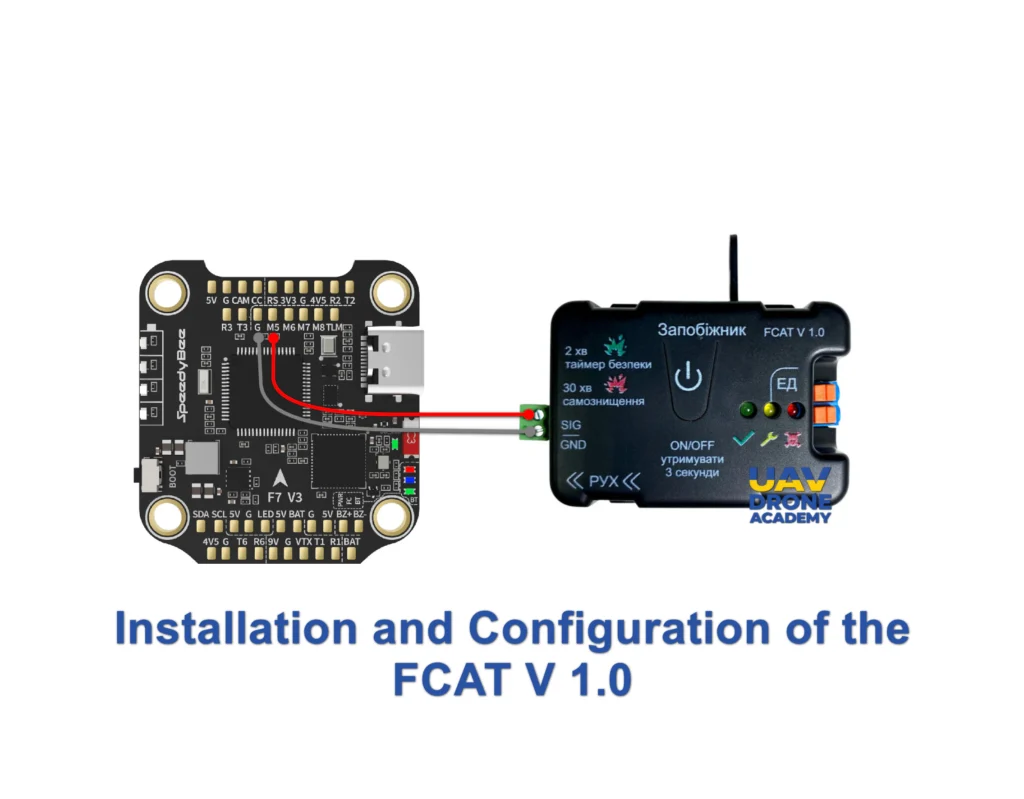
Because the board is self-powered, you do not need to wire power (VCC) from the drone. The connection focuses strictly on communication with the Flight Controller (FC):
- GND: Connect to the Ground (GND) pad on the Flight Controller for signal reference.
- Signal (PWM): Connect the FCAT signal wire to a free output pad on your FC. We recommend using spare motor pads, such as M5 or M6, or the LED_STRIP pad.
- Payload Output: Terminals dedicated to the charge initiator (detonator).
2. Software Configuration (Betaflight CLI)
To enable the M5 pad to send the correct signal, we must instruct the controller to treat it as a user command (PINIO).
- In Betaflight, open the CLI tab and type
resource. - Identify the resource code for MOTOR 5 (e.g.,
B01). - Enter the following commands:
resource MOTOR 5 NONE(releases the pad).resource PINIO 1 B01(assigns the pad to the user command).set pinio_box = 40(defines the activation mode).save.
3. 3-Position Switch Logic (Radio Setup)
Configure a 3-position switch (e.g., SA or SD) on your radio to operate on the corresponding Auxiliary (AUX) channel:
- Position 1 (1000µs): SAFE / DISARMED
- System inactive. The inertial sensor is electronically locked, and manual command is disabled.
- Position 2 (1500µs): ARMED (Impact)
- Activates the inertial sensor. Detonation will occur automatically upon detecting an impact exceeding 10G. This is the standard position for the final phase of an attack flight.
- Position 3 (2000µs): MANUAL DETONATION
- Immediate triggering. Sends the pulse to the board to initiate the charge instantly—useful for airbursts or moving targets.
4. Configuration in the “Modes” Tab
In the Betaflight Configurator:
- Go to the Modes tab and locate USER1.
- Select the AUX channel assigned to your 3-position switch.
- Set the range (yellow bar) to cover from 1400µs to 2100µs.
- Note: When the switch is in the middle (1500µs), USER1 mode readies the board for impact. Moving it to the end (2000µs) sends the manual trigger signal.
5. Safety Protocol and Bench Testing
⚠️ WARNING: Due to the internal battery, the board is live as soon as the physical safety pin is removed.
- Dry Test: Use a multimeter on the output terminals. With the drone armed (propellers removed), verify that the trigger voltage only appears in Positions 2 and 3.
- Safety Pin: This mechanical pin should be the very last item removed before takeoff. It is your physical safeguard against software glitches.
- Failsafe: Configure your radio’s Failsafe so that in the event of signal loss, the AUX channel returns to Position 1 (1000µs), preventing accidental detonations during signal-related crashes.
Legal Disclaimer and Limitation of Liability
The content provided regarding the FCAT V 1.0 initiation board is for educational, informational, and technical purposes only. UAV Drone Academy does not encourage, promote, or assume liability for the misuse, illegal, or unauthorized application of electronic components in explosive devices by unqualified individuals. The handling of payload initiation systems requires specialized training in defense engineering and strict compliance with local and international arms control and aviation laws. By accessing this content, the user acknowledges that they are solely responsible for their actions and for adhering to all operational safety standards and legal regulations.